🔗 Quick links
- iButton probes come in many forms, some have LED-indicator(s) with one or two colors.
- iButton probes have at least two wires: a data line and a ground. Other wires are for indicator LED(s).
- iButton probes with two-color LED-indicator usualy have one bi-directional LED that changes color when polarity on two available LED-wires is reversed.
- On this page are some examples of iButton probes with their wiring. Wiring may vary for the model you receive.
No probe? No problem…
iButton probes are essentially just connecting the two parts of an iButton cylinder to wires, so you can simulate a probe and setup like this:
- Connect the flat circular surface of the iButton to an Arduino digital pin, this is the 1-Wire data line.
- Connect a 2200 Ω to 4700 Ω pull-up resistor between the 1-Wire data line and Arduino 5V pin.
- Connect the side of the cylinder of the iButton to an Arduino ground (GND) pin.
Examples
Looks the same as one color model, see below. Different colors of LED-indicator by reversing polarity.
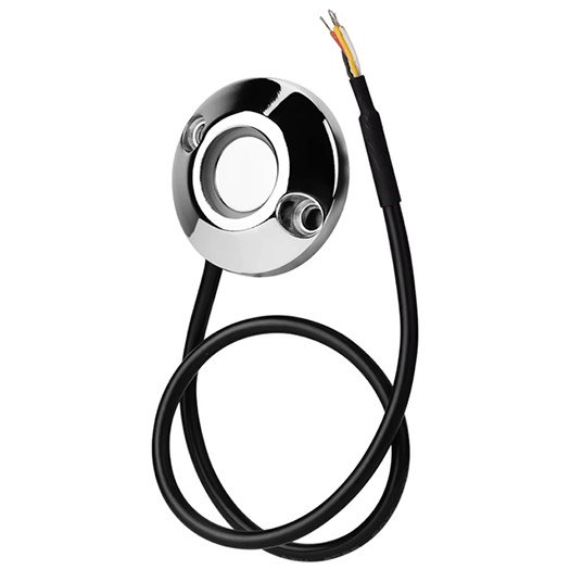 |
Color | Function |
| Red | 1-Wire Data |
| Green | LED+ (red) / LED- (green) |
| Yellow | LED- (red) / LED+ (green) |
| Black | 1-Wire Ground |
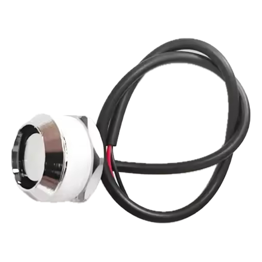
Looks the same as two color model, see above.
|
Color | Function |
| Red | 1-Wire Data |
| Green | LED+ |
| White | LED- |
| Black | 1-Wire Ground |
 |
Color | Function |
| Green | 1-Wire Data |
| Black | LED+ |
| White | LED- |
| Red | 1-Wire Ground |
 |
Color | Function |
| Red | 1-Wire Data |
| Black | 1-Wire Ground |